Monday, 24 September 2012

555 Timer Circuit - Astable Mode


Astable means not stable in any state, so this circuit will alternate between on and off and create a square wave output. The on and off times can be adjusted by changing the values of R1, R2 and the capacitor. This changes the RC time constant.

  • The three resistors at the top of the 555 timer create a voltage divider to give 1/3 and 2/3 of the supply voltage.
  • When the supply voltage is switched on, the SR flip flop is currently unset, not Q will be high and so the transistor will be saturated and the current will just flow to ground and the capacitor will not charge.
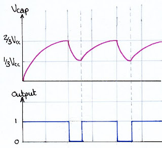
  • When the trigger voltage (this could be seen as the input) – Pin 2 – falls below 1/3 of the supply voltage the first comparator saturates, setting the SR and not Q will be low. This means that the transistor will not be saturated and the current will flow through the capacitor and it will start to charge. The inverting amplifier will invert this low signal and the output – Pin 3 – will be high. (The first “on period” will be longer as the capacitor is charging from 0, after this it charges from 1/3 so will settle into a repeated pattern)
  • When the voltage over the capacitor (and therefore the threshold voltage – Pin 6) reaches 2/3 of the supply voltage the second comparator will saturate positively, resetting the SR, not Q will be high and the transistor will saturate. Because of the potential difference over the charged capacitor, current will now flow through pin 7, through the transistor to ground, discharging the capacitor. The inverting amplifier will invert the high signal and the output – Pin 3 – will now be low.
  • As long as the trigger voltage – Pin 2 – remains below 1/3 of the supply voltage, the first comparator will remain saturated and so the set to the SR will be high and so as soon as the reset pin is low (because the capacitor has discharged and so the voltage to the + terminal of the second comparator will be lower than 2/3 of the supply voltage and therefore it will saturate negatively) the SR will set and the whole cycle will start again.


Wednesday, 12 September 2012

Structures and Materials - Tips

The NAB will consist of questions simliar to those done in class/homework and focusses on outcomes 2 and 3.

Most obviously the best advice I can give is READ THE QUESTION!  But here are some other things to remember when tackling structures questions:

Unit 2 - Bending Moments, Shear Force and Bending Moment Diagrams
  • Draw your diagrams clearly on squared paper and rememer to label everything. Check that your free body diagram at the top is right before going further.
  • Remember that UDLs will create a slope on your shear force diagram, and point loads (including reactions) will create vertical lines.
  • The Maximum Bending Moment occurs where the shear force diagram crosses the axis.  Draw this point up to you free body diagram as well as down to the bending moment diagram so that you have an idea of the distance you expect to get through your calculations.
  • Always draw the maximum bending moment onto your bending moment diagram.
  • Remember that the bending moment diagram will be flat where there is only point loads, and only curved under a UDL.  Make this clear on your diagram if you have a combination of them both.
Unit 3 - Method Of Sections
  • Calculate your reactions first. Remember to take moments about a hinge first (external forces only) and then use an up, down, right, left diagram to calculate the the hinge reaction. (Be careful with sloping forces.
  • Choose the half which is easiest to keep.  Lose the hinge reaction where applicable, or the side with the most forces in it. 
  • Forces which act through the node create no moments, so make sure to choose nodes in order to give you one unknown only.  Try to work systematically
  • Remember that you can take moments about a node which is not part of the section you have kept.
  • DRAW ALL NODE DIAGRAMS SEPARATELY Clearly show all forces in the cut members as ties and this makes working out perpendicular distances easier as you can focus on one part at a time.
  • Draw on your perpendicular distances so that you can be confident that you are working with the correct numbers.

Tuesday, 28 August 2012

Structures 1 - Beams and Bending

Unit 1 looks at beam structures and how they react when loaded.  You need to be able to define: bending moment, moment of resistance and second moment of area.  You also need to understand the principles in what happens internally to a beam when it has been bent and be able to use the beam equation:

M/I = E/R = σ/y

(Where M = (bending) Moment, I = Second moment of Area, E = Young's Modulus, R = Radius of Curvature, σ = Stress and y = distance from the Neutral Axis to the tension edge.)

You will also need to use the equations and/or information in the data booklet to calculate second moment of area, and the maximum bending moment and maximum deflection for different configurations of beams and loading.


You may find the following websites/resources useful to supplement your printed notes:

http://www.freestudy.co.uk/d209/t2.pdf


toolboxes

Monday, 27 August 2012

Welcome to Advanced Higher Technological Studies

Welcome all!

I hope that you will enjoy the next year of Advanced Higher!

This is our course structure:


  • Structures (1/2 course)
  • Applied Electronics
  • Systems and Control
  • Case Study (1/2 course)
Please let me know if there is anything you would like me to post here to help further your understanding of the notes you have been given, or what has been said in class.